
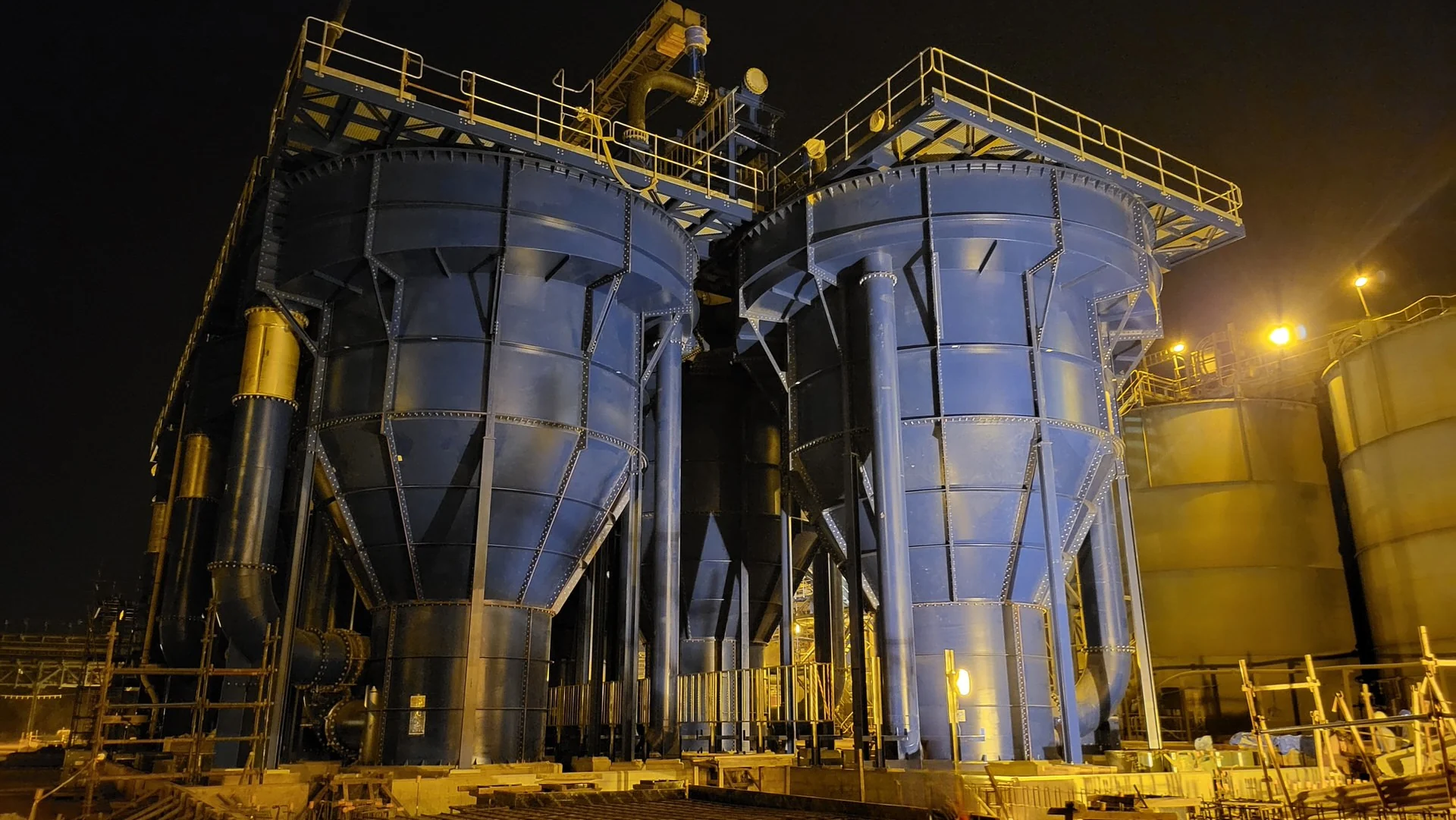
AZTEC UpFlow Reactor · AZ-UFR
More gold.
Lower cost.
Cleaner tailings.
Proven reactor technology for higher gold recovery, lower operating cost and reduced environmental impact, engineered to integrate after your existing circuit.
The commercial case
Three outcomes that move project economics
The AZ-UFR is designed to improve the numbers that matter to operators and investors, working on the tailings and slurry you already process.
Higher gold recovery
Accelerated reaction kinetics drive faster leaching and adsorption, recovering additional gold from the slurry already moving through your circuit.
Lower operating cost
Reduced detox reagent consumption lowers OPEX, while efficient energy distribution removes the need for large-scale agitation and complex control systems.
Reduced environmental impact
Lower free and WAD cyanide concentrations in the treated slurry support ICMI-aligned tailings management and reduce environmental load.
A new generation of reactor, without the agitator
The AZ-UFR replaces the conventional agitated tank. Instead of relying on large-scale bulk recirculation, it uses a novel counter-current flow that directs overflowing slurry back into a compact, high-intensity mixing chamber at the reactor base, where the primary reaction kinetics take place.
The geometry distributes energy according to particle size and density, so each fraction of material reports to its optimal kinetic zone. The result is an energy-efficient, high-performance system that maintains stable hydrodynamics across a wide range of slurry densities.
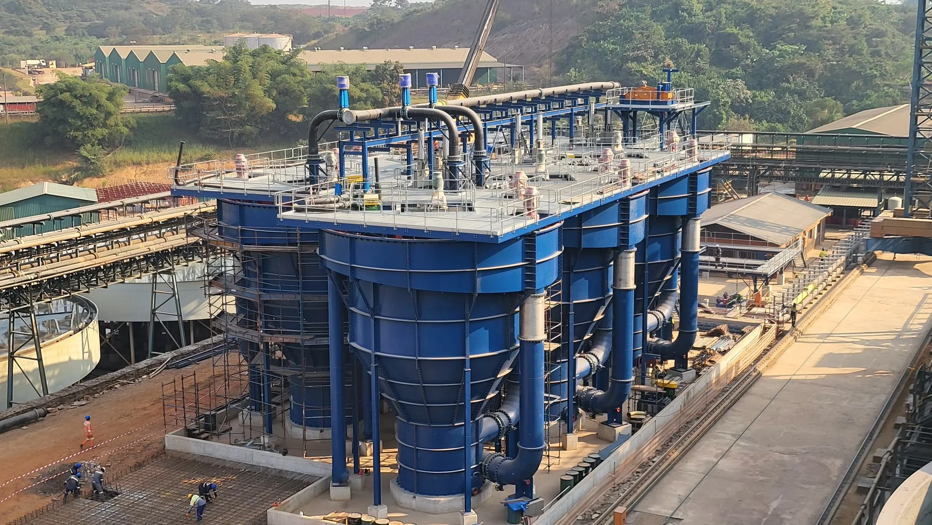 AZ-UFR · plant installation
How it works · counter-current mixing
Energy concentrated where it makes the greatest impact
The reactor is named for what it does: it drives slurry upward through a controlled counter-current, concentrating energy at the base rather than spreading it across a large agitated volume.
Feed enters the reactor
Slurry from the preceding circuit enters the vessel and begins its path through the reactor body.
Counter-current flow returns to the base
Overflowing slurry is directed back down into a compact, high-intensity mixing chamber at the reactor base, the opposite of conventional bulk recirculation.
Energy is distributed by particle
The geometry automatically distributes energy by particle size and density, so each fraction reports to its optimal counter-current kinetic zone.
Reaction and recovery
Primary reaction kinetics take place with high efficiency, no conventional agitators, and no complex control systems to manage.
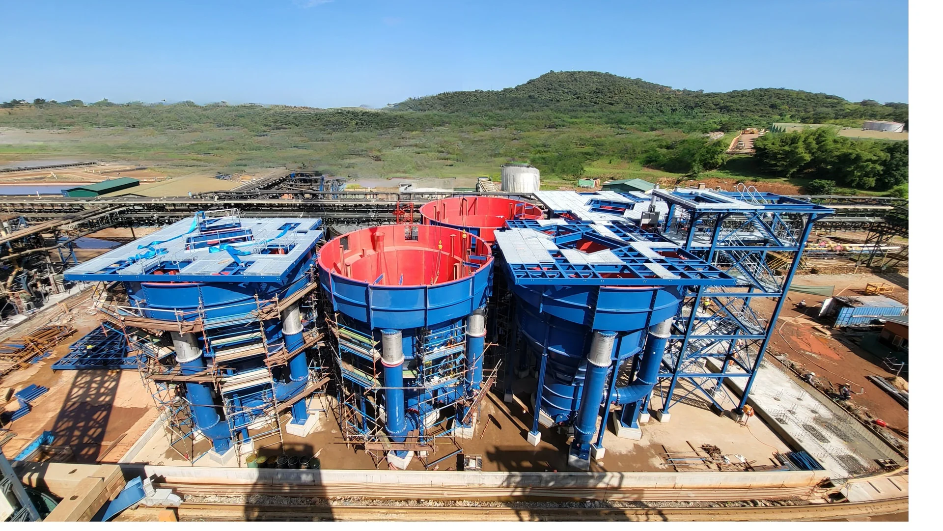 Vessel geometry, aerial
Where the AZ-UFR differs from an agitated tank
A qualitative comparison of the reactor's design approach. Mine-specific performance is established through testwork rather than generic figures.
| Characteristic | Conventional agitated tank | AZTEC UpFlow Reactor |
|---|---|---|
| Mixing method | Mechanical agitator, bulk recirculation | Counter-current flow into a high-intensity base chamber |
| Energy distribution | Spread across a large volume | Concentrated by particle size and density |
| Control systems | Typically required | No complex control systems |
| Slurry density range | Constrained | Stable across a wide range |
| Restart after power loss | Can require intervention | Seamless restart |
| Construction | Varies | Fully bolted for faster installation |
| Maintenance | Agitator drivetrain | Replaceable pump impellers |
Evidence, not estimates
Performance is quantified for your orebody
AZTEC does not publish generic percentages. The value of the AZ-UFR is established on your own material through onsite testwork. These are the three measures that testwork quantifies.
Gold recovery uplift
Additional gold recovered from the as-arising tailings discharge, measured against your current circuit performance.
Quantified by testworkOperating cost reduction
Change in detox reagent consumption and associated OPEX, modelled from the measured cyanide reduction.
Quantified by testworkCyanide reduction
Reduction in free and WAD cyanide concentrations in the treated slurry, supporting ICMI-aligned management.
Quantified by testworkPositioned after CIL/CIP or cyanide detox
The AZ-UFR circuit is located after the CIL/CIP or after the cyanide detox circuit, recovering additional gold from the tailings discharge before it reports to the tailings storage facility.
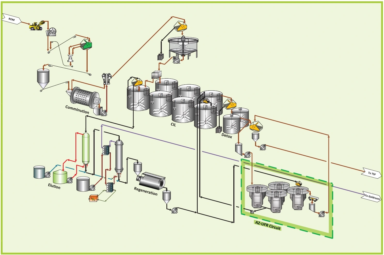
Drawing ref: AZT-0000-PR-OFS-001 · issued for information. Supplied by AZTEC.
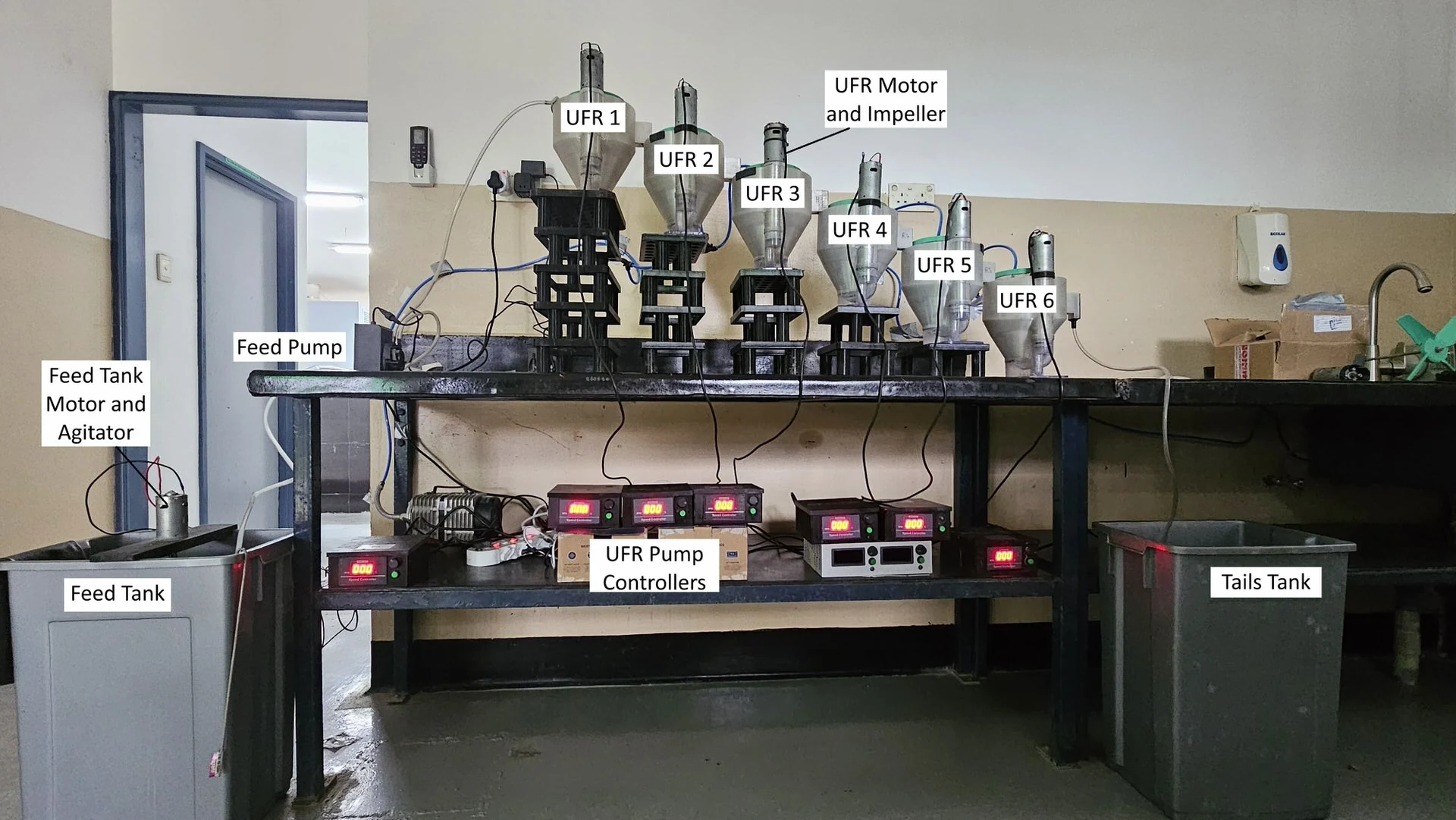 Pilot testwork rig
De-risk the decision before you commit capital
Onsite testwork validates the design parameters for your orebody and circuit, and feeds the financial modelling used for feasibility and investment analysis.
It is how the recovery, cost and environmental outcomes are quantified for your operation, before any capital decision is made.
Engineering support across the project lifecycle
AZTEC supports the AZ-UFR from first evaluation through to long-term operation.
Financial modelling
Feasibility and investment analysis built on measured testwork data.
Onsite testwork
Validation of design parameters to de-risk the capital decision.
Custom engineering
Solutions configured for optimal integration with your plant.
Spares and aftermarket
Long-term support and spares supply for operational continuity.
AZTEC is developing further technologies for mineral processing
A number of these are still in development or undergoing patent processes. Availability and status will be confirmed.
Start here
See what the AZ-UFR can recover from your tailings
Request mine-specific testwork and receive a validated basis for the recovery, cost and environmental case.